
- Home
- About
- Services
- Air Blow Cleaning Services
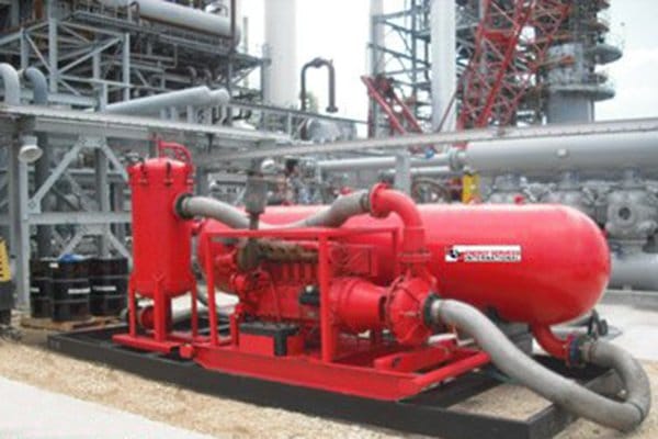
- Oil Filtration Services
- Chemical Cleaning
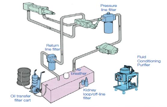
- Filters & Breathers
- Fluid Reconditioning Services
- Hydraulic System Decontamination
- Hydrolazing
- Hydrostatic Testing
- Oil Flushing
- MHC & EHC Flushing
- Reservoir and Tank Cleaning
- Steam Blowing
- Varnish Mitigation & Removal
- Additional Services
- Equipment Fleet
- Our Brands
- Projects
- Get A Quote
- Contact
Author: Lynn Elliott

Optimizing Maintenance of Gas Processing Facilities
Regular maintenance and lubricant reconditioning of critical gas processing equipment can extend the life of your critical components, reduce oil replacement costs, and prevent the major causes of equipment failure.
Which services should you be performing and how often? The chart below lays out an optimal maintenance schedule for Gas Processing Plants. Use this as a guide for setting up your maintenance program:
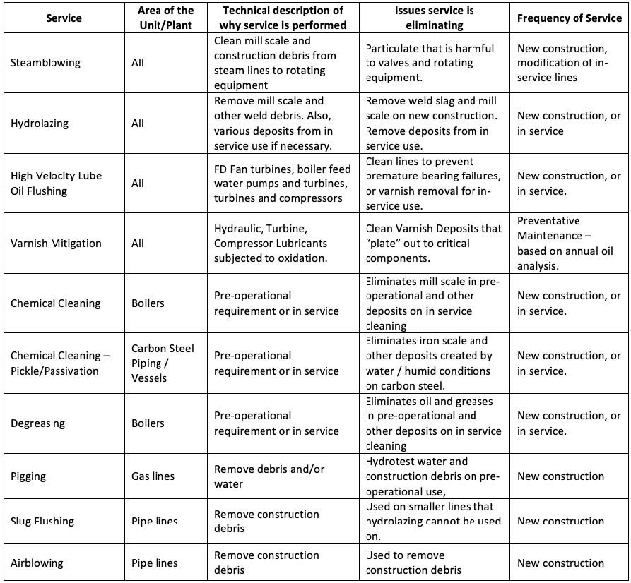
Table 1. Maintenance Schedule for Gas Processing Plants
EMBEDDED TECHNICIAN PROGRAM
If you don’t want to have to worry about tracking and upkeeping these reliability services yourself, the Reliable Industrial Group (RIG) philosophy is to embed a full-time technician to support your plant’s maintenance and reliability ambitions. Current Programs may include MLA or MLT trained personnel to perform services including:
- On site reclamation of hydraulic fluids
- Air breather supply and replacement
- Oil filter supply and replacement
- Oil sampling
- Oil sample report review
- Inline filtration, dehydration, and varnish mitigation
- Documentation, maintenance reporting, cost savings analysis
RIG’s embedded technician program is not limited to the above services. We can customize a number of reliability programs to meet the safety and reliability goals of your facility.
CONTACT RELIABLE INDUSTRIAL GROUP (RIG)
To work with the industry leader in plant reliability and maintenance services, call 800-770-4510 today or learn more at www.theRIGteam.com.
Preventing Bacterial Growth in Your Turbine
Bacteria colonies are a growing and expensive problem
As steam turbines throughout the United States age and maintenance intervals are pushed out, preventing bacteria growth inside turbines is becoming ever more important. Bacteria colonies can affect oil quality, produce corrosive by products, and clog control systems which can result in significant repair costs.
There are three main types of bacteria that grow in lube oil systems:
- Sulfate Reducing Bacteria (SRB), which are anaerobic bacteria that survive off sulfate
- Acid Producing Bacteria (APB), also anaerobic and ferment sugars, usually light organic acids
- General Aerobic Bacteria (GAB), which require oxygen to survive and grow
Specific conditions must exist for the bacteria to develop and grow. Water must be present, but as little as 0.5 mL of water per Liter of turbine oil can do the trick. Organic material (carbon, nitrogen, phosphorous), optimum temperatures, stagnant or low flow areas of the system, suspended particles, and emulsification of the oil are the other key ingredients. The presence of oxygen will act as a accelerant, speeding up bacteria growth. But how do you know if these conditions have developed in your turbine?
Operational Signs of Bacterial Growth
Lab analysis is the best way to confirm the presence of bacteria and the only way to know which type you have. But, there are some other signs and symptoms you can look for:
- Do you see any clear, silicone colored gel inside the site glass of your oil filtration skid?
- Are your filters frequently plugged with a jelly substance? What about your control orifices or lines?
- Are you controls slow to respond or under responding? Have you had a unit trip recently?
- Have you been operating for prolonged periods with water levels greater than 500 ppm?
- Are you seeing emulsified oil or an oil/water mix that will not easily separate?
- Has your turbine failed any of these tests recently?
- Water demulsification test (ASTM D1401)
- Turbine oil foaming characteristics test (ASTM D892)
- Relatively rapid turbine oil oxidation as measured by the RPVOT test (ASTM D2272), especially if the oil has not been overheated
- Do you see any isolated, concentrated rust spots on metal parts of filter ends, turbine bearing components, and so on?
How to Remove Bacteria from Your Turbine
If you do suspect you have a problem, or even if you just want peace of mind and simple want to check, here’s what you should do.
- Confirm the presence and type of bacteria with the help of a fluid analysis lab. Don’t know a good lab? We can help with that. Simply call us at 1-800-770-4510 and we can be on-site within 24 hours or less.
- Remove the contaminated oil. Do not use in-plant piping during the oil removal – this will only increase the risk of spreading the bacteria.
- Inspect and clean the lube oil systems, dissembling and cleaning major components, especially reservoirs and filter housings.
- Have a high volume, high temperature oil flush performed on the system. Do not use old oil for this flush! Bacteria, bacteria, bacteria!
- Refill the system with new oil
- Add recommended biocide to the lube oil
What Oil Flush Should I Use?
Knowing the difference between oil flushes, when to use which, and the proper terminology to describe them is key to extending your equipment life. While our certified field technicians are exceptional at making sure the right flush is applied every time, it is important to us that our customers understand what is happening with their lube oil and are integral part of the overall oil cleanliness management plan.
The main categories of oil flush are:
1. High Velocity Flush
With a descriptive, memorable name, this is the type most customers have heard of. It is the best approach to take during all major maintenance, system failures, or when you large amounts of contaminants/debris are in the system. It is the most effective at removing all lingering materials and particles. High velocity flushes create chaotic flow within the system, breaking off and removing any unwanted, clinging debris. The violent nature of this action requires that bypasses for sensitive system components such as pumps, valves, bearings, orifice plates, accumulator bindings etc. are protected during the flush. Verify results with inspection screens/media and particle counts.
One misconception about this process is that high velocity occurs when high turbulent flow is achieved. While turbulent flow can be achieved at Reynolds numbers around 4,000, this is normally not enough turbulence to remove all damaging debris. Most high velocity flushes target a Reynolds number of 20,000 or 2-3 times the normal system flow rate.
2. System Flush
Most appropriate for light maintenance work and non-critical systems, this flush utilizes system pumps. Like with high velocity flushing, all critical components should be bypassed with jumper hoses and protected. Using system pumps to flush out foreign material will take longer than using an external pump, which is why this method is not recommended for turnarounds or maintenance with a strict deadline.
3. Circulation Filtration
A system in production can undergo circulation filtration, with pumps running in the normal flow pattern. Circulation filtration is limited in scope, but can successfully clean reservoirs or aid in filtering/changing lubricants. External filtration off a reservoir is the typical approach. It is appropriate for annual maintenance, but not for any outage that includes pipe breaks or the opening of bearing housings. Verify results with a lab analysis or field kit.
4. Rinse/Purge
When changing lubricants or displacing cleaning chemicals (including detergents), a rinse/purge flush is often utilized. The procedure includes draining the system, refilling the reservoir to the minimum circulation level, and then using the system pumps to circulate oil in a normal flow pattern. Usually only a particle count is needed to verify, but labs or field kits may be used if employed during a varnish mitigation procedure.
We always recommend consulting with an oil flush expert if you are unsure which oil flush is appropriate or how to remove contaminates from your system. However, you should have an annual maintenance plan that involves regular lube oil flushes to control ISO cleanliness levels. If you don’t have one in place now, speak to one of our certified technicians about mapping one out and getting into place, or check out our blog on how to develop one.
Source: Larry B. Jordan
What is Pre-Commissioning and What Does it Include?
Pre-commissioning is a critical project phase that takes place following the construction of piping and process systems, but before those process products are introduced into the systems. The purpose of pre-commissioning is to safeguard the integrity of your systems and ensure they don’t have debris or contaminants that can damage equipment and delay system startup.
Pre-commissioning:
- Helps ensure project ROI
- Reduces startup delays
- Ensures the operability of critical equipment, which maximizes system uptime
In this post, we cover the most common pre-commissioning methods for cleaning your system of mill scale, debris and other contaminants. It’s important to note, when you enlist a service provider to handle pre-commissioning for your system, these techniques should be customized to your system.
Air Blow Cleaning
- In air blowing, air is pumped through your system at more than 1.5 times PSI above normal operation, creating a drag force that removes debris
- The process involves specialty equipment to pressurize the system, including: air receivers, quick-opening valves, oil-free, dry compressed air and fittings and hoses
- Once pressurized, stored energy pushes out debris in a controlled manner so it doesn’t damage expensive equipment downstream
- Air blowing is the simplest, fastest, and least expensive cleaning method
Learn more about our air blowing services.
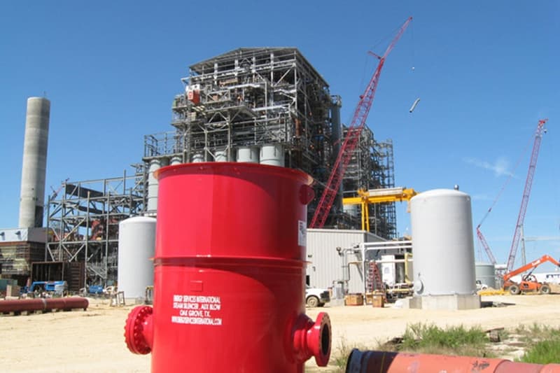
Steam Blow Cleaning
- Steam blows are necessary for most steam lines and turbine systems
- In this process, high-pressure steam is blown through temporary piping toward steam receivers to remove debris, usually at 1.2 times PSI above normal operation
- There are multiple approaches to steam blows, including the puffing method and the continuous blowing method
- There are significant noise and temperature hazards that require a strong process to control — learn more in this article
Learn more about our steam blowing services
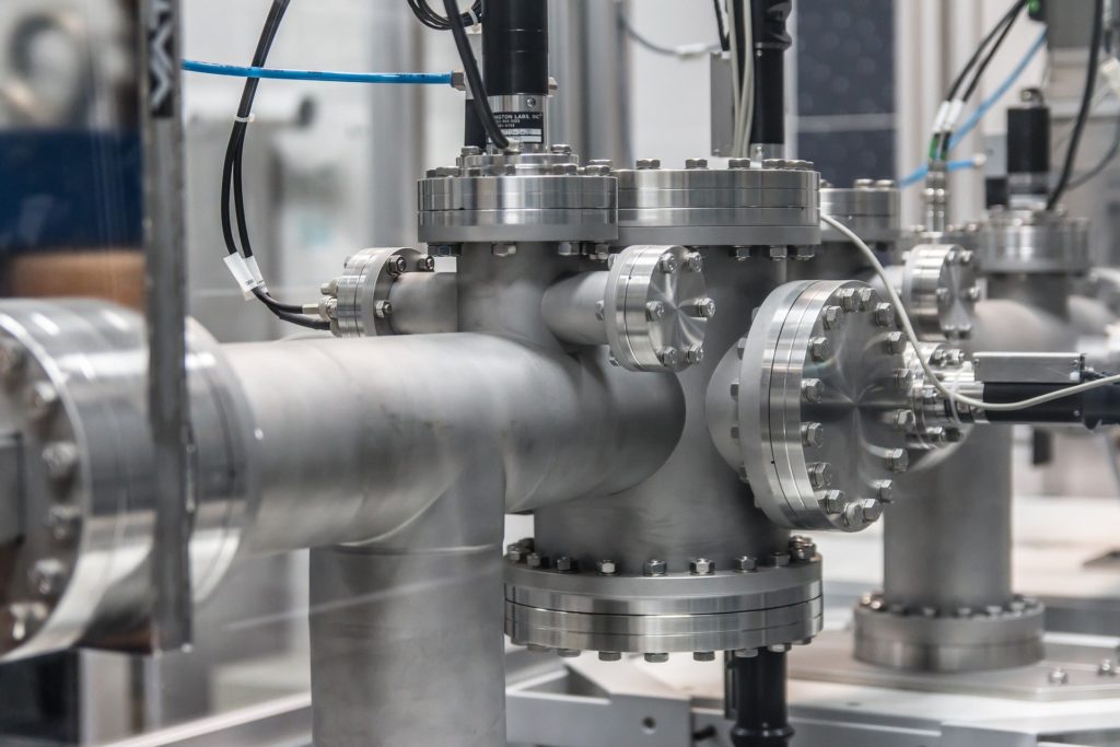
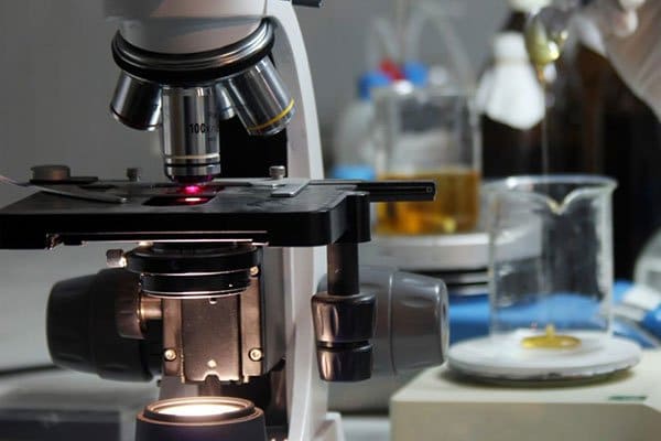
High-Velocity Oil Flushing (HVOF)
- All rotating equipment must be cleaned and prepared before going into operation
- For large-scale operations, a high-velocity oil flush (HVOF) is the most common method
- In this approach, lube oil is run through your systems and filtered out, bringing contaminants with it
- This requires system and turbulent flow analysis as well as a detailed flushing plan to ensure success
- System cleanliness is proven using automatic particle counters or manual microscope analysis on filter paper, depending on the system
Hydrostatic/Leak Testing
- Following cleaning of tanks, piping and vessels, it’s crucial to test the system’s structural integrity and ensure there aren’t leaks
- This can include pneumatic testing, hydrotesting, helium leak detection and other approaches
Learn more about hydrostatic testing services
Chemical Cleaning
- Chemical cleaning is used on pipe systems to remove surface contaminants
- It dissolves soluble debris and absorbs them into a solution
- It’s crucial to get this procedure right, as without proper planning, filtration and removal, it’s easy to leave debris behind
- It’s particularly important to select the correct, OEM-approved cleaner for your system
Learn more about the chemical cleaning process from this guide
Fluid Pumping
- High-velocity flushing can also be used on large bore piping to remove debris
- The same approach is used for boiler feed water flushing, glycol flushing and water flushing
Dewatering
- Dewatering is the process of removing water from solid material
- There are several approaches, including: centrifugation, filtration and other liquid separation approaches
- Dewatering is a simple process, but must be handled with care in order to protect the environment from unexpected spills
System Filtration
- Many pre-commissioning services require filtration
- One approach is to set up a slip stream on a live system
- Sometimes, if heavier-duty filtration is required, it’s necessary to connect external filters full bore into the system
Selecting a Pre-Commissioning Service Provider
As pre-commissioning is such a crucial part of a project process, it’s best to use a professional services provider. We recommend selecting a professional partner to:
- Design, manage and execute pre-commissioning strategies
- Achieve cost-effectiveness, scheduling, quality and reduction of project risk
- Bring experience, knowledge and integrity
- Have an experienced, professional team of field staff
- Have experience working with companies like yours
At RIG, we take pride in delivering excellent pre-commissioning services and ensuring our clients’ success.
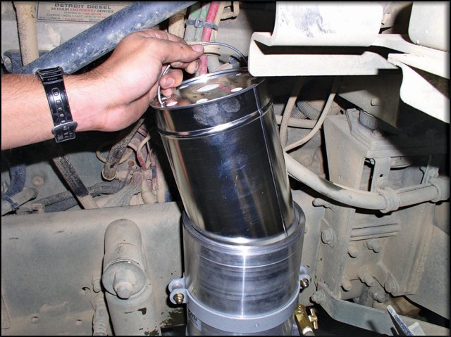
High Differential Pressure Doesn’t Always Mean A Plugged Filter
A high differential might not mean your filters are plugged. If you keep replacing filters and are still experiencing the same problem, or if your filters do not look clogged when you pull them, it’s time to consider some other data. Changes in fluid viscosity and excessive filter replacements can give false end-of-filter life warnings when the system is not calibrated correctly.
Case-in-point: RIG recently performed a high velocity, hot oil flush on a small compressor and electric motor package. After achieving an API-614 acceptable screen based on piping size and a lubricant ISO cleanliness code of 15/13/9, we helped the customer install filters in their on-board filter housings and install screens with cotton sheets in the supply headers to run their auxiliary pumps for verification through the bearing headers.
It was determined after start-up by the plant that the 10 um filter used plugged, at which time it was changed out for a new element. Knowing the system was clean, but not seeing the differential and operating factors, we knew something was not right about the findings.
Later, we performed the same flush on a similar system at which time we monitored flow and differential factors to repeat the process and use data to determine the performance factors of the filters.
Step One: RIG removed the filters from the housings, installed jumpers at the bearing supply headers and began flushing using our 400 GPM flushing skid. This proved a 19 psid differential across an empty filter housing with 30 psi system header pressure and oil temperature of 70°F. This would show a 63% filter life used giving the filter change out differential of 30 psid.
Step Two: After the system was cleaned by flushing and achieving the API-614 pipe cleanliness standard, along with the targeted ISO Fluid Cleanliness spec, the decision was made to add a filter and use the on-board aux pump in conjunction with our flushing skid. Based on understanding of flow differential, we knew we should gain anywhere from 1–6 psid with the new 10 um filter installed after start-up.
Step Three: The pumps were started and the bearing headers were still jumped so the only resistance we would encounter from the previous step was the filter and it would prove to be slightly less since the lubricant was at 150°F and the viscosity had dropped to 17.7 cSt. This proved out and we achieved a system pressure of 34 psi and a differential pressure of 23 psid, which would show 76% of used filter life with a change out differential requirement of 30 psid. This was a gain of 4 pounds of differential from adding a filter to the housing even while dropping the viscosity of the oil from 46 cSt to 17.7 cSt.
Step Four: After the system was circulated, using this process, the decision was made to install the bearing headers to the equipment and install a 100 mesh screen with cotton bed sheets to the supply piping after filters. This is where data helps provide a logical explanation of why the filter is not plugged. After installing the bed sheets and screen, we now add more resistance immediately after the filter housing, this will make the system header pressure increase to nearly 99 psi and the post filter pressure at 60 psi which proved a 39 psid across the filters with the lubricant at 80°F, which showed 132.64% of filter life used. After a few minutes, the operators shut down the system and wanted to change the filter, but it was explained that the screen with linen sheets were installed which created the differential from pump supply to filter outlet and asked them to continue running the pump for the duration of an hour so we could check the screens.
Step 5: The screen was pulled from the supply header and the system was restarted for circulation without any restrictions except operational flow orifices. After reading the header pressure and differential. It was concluded that the filter only had a differential of 8.7 psid and a system pressure of 36 psi.

Developing the Right Oil Flushing Plan
What is the right acceptance criteria to use for oil flushing activities?
For clients, new to the world of oil cleanliness and flushing it is easy to get confused by the nomenclature. Those more seasoned professionals will throw out abbreviated words, acronyms, or API (American Petroleum Institute) Standards; like everyone has read and memorized all 300 pages of each standard. Here at RIG it is our goal to be the technical resource needed in executing flushing services. There is key information needed while developing the right flushing plan for each piece of equipment. Let’s break down each piece.
Does the OEM (Original Equipment Manufacturer) have a specific guideline to use for flushing activities on the rotating equipment? Most OEM’s do have criteria for commissioning and some include general guidelines for maintenance
- Is equipment under warranty? If yes, OEM specifications supersede API standards. Each OEM is different.
RIG works with the client and OEM to develop the right plan to meet cleanliness criteria. - Has rotating equipment been modified where original OEM specifications are no longer valid? Not a typical situation but not totally unheard of. You would review the modified piece specifications and set criteria to the tightest (most stringent) specification.
- Has the site or plant developed their own criteria? We have seen this happen with larger corporations who share best practices on a national (and sometimes international) level. This situation usually take place when companies have had failures due to lubrication cleanliness issues. RIG experts have assisted in development and revisions to “Best Practices” alongside these companies. Focusing on prevention first, then executions of flushing during downtime to maintain cleanliness.
- Is the unit from 50+ years ago and no one has the specifications anymore? Or, is the criteria outdated and no longer best practices? This is the most common situation we run into today. Units from the 1950 and on are still in use today. Far out of warranty and flushing in the 50’s consisted of running some oil through the system and out the other side to disposal.
If you are in a situation with no obvious criteria from manufacturer what is the right direction? There are (5) key documents issue by ASTM (American Standard for Testing and Materials).
- API 686 – Machinery Installation and Design, Chapter 8 – Lubrication Systems Installation
- ASTM: D 4174 – Cleaning, Flushing, and purification of Petroleum Fluid Hydraulic Systems
- ASTM: D 6439 – Standard Guide for Cleaning, Flushing, and Purification of Steam, Gas, and Hydroelectric Turbine Lubrication Systems
- API 614 – Lubrication, Shaft Sealing and Oil Control Systems and Auxiliaries
- ISO (International Standard Organization): 10438-1 – Petroleum, petrochemical and natural gas industries – Lubrication, Shaft Sealing and Oil Control Systems and Auxiliaries (Note: ISO10438-1 was developed jointly with API614 and is equivalent to)
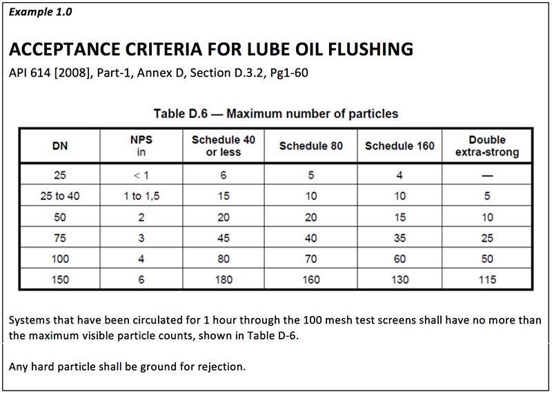
The most utilized standard is the API614 for specific acceptance criteria (see example 1.0). All of the listed documents have useful information on what to flush in the system, inspection media, and minimal flow rates. However, these documents do not always take into account newer “Best Practices”. For example, a pneumatic vibrator will shake the pipes without damaging paint or scuffing fittings that “hammer blows” do. Or, in place of system pumps bringing in one of RIG’s high volume flushing skids. Increase volume will eliminate days of flushing utilizing flow to 2-3 times normal operating level. This will develop turbulent flow and a higher Reynolds number than can be achieved with system pumps.
At RIG our goal is to become an extension of your Reliability and Maintenance Teams. Providing that technical expertise in Lubrication Services.
If you would like to learn more about RIG, contact Jason Bandy at [email protected] to schedule a Lunch and Learn at your facility today.
By: Larry Jordan
Why You Need a Quality Filtration Program
How many different lubricants are used throughout your plant? What does your OEM manual recommend for each piece of machinery within your plant? Which bottle of lube oil is oldest? What is the date of the last oil top-off for each piece of equipment? What about the last oil analysis?
If you cannot easily pull up all of this information, then it’s time to consider a Quality Filtration Program (QFP). Not only does a QFP make it easy to answer all the questions above in a matter of minutes, but they provide the following long-term benefits:
- Extending equipment life by helping ensure every piece of equipment has the right lubricant that’s in acceptable condition, and that the lubricant is being applied correctly, at OEM recommended intervals, and in OEM recommended amounts.
- Reducing overall lubricant costs by efficiently managing lube oil purchases (knowing when you need to purchase and how much) and preventing unused oil from accumulating and sitting until past expiration.
- Helping you identify where changing specific systems and machinery to a different lubricant can help you save costs and simplify plant operations. Often you can consolidate the types of lubricating system required by the plant by reviewing OEM manuals and identifying machinery on rare lubricants that can be converted to a shared lubricant, simplifying your lubricant purchases and often saving time and money moving forward.
- Helping plant maintenance personnel upkeep machinery more efficiently but organizing all pertinent information in one master document and scheduling preventative maintenance tasks at appropriate intervals.
- Improving plant safety by ensuring all lubricant handling safety practices are documented and in place.
- Identify costly machinery and mishandled maintenance faster through fully documentation of all lubrication related tasks and costs over time. if expected costs are being exceeded by certain pieces of equipment, or under/over maintenance is occurring, you will now be able to see that because you will have a planned baseline to compare to.
- Maximizing lubricant analysis reports by establishing lubricant program goals and key performance indicators. These performance metrics will help see progress overtime and keep everyone focused on improving overall lubricant and machinery health as you move forward.
Best Practices for Implementing an Effective Quality Filtration Program
A good quality filtration program has four basic steps. You might already have some type of filtration program or be doing some of the items mentioned below. Or you could be starting from scratch. Either way, we have outlined best practices that you can follow to create a program or check your current program against.
Step 1: QFP Development
To develop a robust program, you will need to create all of the following:
- A full equipment list of all machinery to be included in the lubricant program listing (at minimum) equipment identification names, numbers and process descriptions. This list should go beyond pumps, motors and compressors, and include any and all equipment requiring lubricant in the facility.
- Plant lubrication survey which is a detailed lubrication inspection of all plant equipment. You will want to review each machines OEM manual, current state of operation, current maintenance practices, and all related characteristics. This should take several weeks to complete.
- Lubricant selection & consolidation goes hand-in-hand with the survey. During the survey you will want to note all the lubricants currently in use. Then, you will make a consolidated list of lubricants and review that list for opportunities to reduce the total number of lubricants that will be used in the program. If only a few pieces of equipment use a certain brand or grade, see if safely change out that lubricant for another more common lubricant. The lower the number of lubricants used, the less overall work moving forward, from documentation to purchasing.
- Plant lubrication manual – you should consolidate all the lubricant information you’ve collected so far into an electronic plant lubricant manual. This manual will be your master document for all lubricant related information, and will updated with any changes moving forward. At minimum it should include; equipment numbers and descriptions, equipment pictures, lubricant sections from OEM manuals, and selected lubricants technical data sheets and Material Safety Data Sheets (MSDS).
- Purchase necessary lubrication equipment for storing and applying lubricants safely. Equipment may include storage racks, plastic heavy duty storage containers, grease guns, filter carts, and bulk storage containers.
- Set lubrication Preventive Maintenance (PM) frequency to generate a service schedule. Remember to include the following services; lubrication inspection and top off, visual inspections of equipment, equipment temperature readings, and oil sampling schedule.
Step 2: QFP Rollout & Implementation
After you have gathered all the necessary information, you will need to enter information in the plant’s Computerized Maintenance Management System (CMMS) or Enterprise Asset Management (EAM) system. Next, set the Preventive Maintenance (PM) and task frequencies and create the clear and concise lube routes.
During implementation, you will need to ensure safety procedures are in place for the lubrication program. Make sure safety practices are both documented and have been reviewed recently with all plant personnel. You should also check that following are in place:
- MSDS (Material Safety Data Sheets) are available and are reviewed.
- Lock out procedures are followed
- Leaks are under control
- Spill response in place
- Handling practices maintain a safe environment
- Lubrication Equipment use is understood
- Sampling procedures are followed
Finally, you will need to make sure anyone working with lubricants is properly trained and can follow the new procedures and schedules. Make sure every step in the process is well documented, accessible by all employees who need it, and gives clear instructions, safety guidelines, purposes and desired outcomes.
Step 3: On-going Program Management
Once everything is flowing in the right direction and the program has been successfully rolled out, you must continue to actively manage the Quality Filtration Program for success. Make sure you have a plan for who is accountable for the programs success moving forward. That person should be ensuring all scheduled tasks actually happen and are properly documented for a reliable work history in your CMMS or EAM. This work history will become the primary source of information for finding problems and improving lubricant management moving forward.
Step 4: Goal Reviews & Program Improvements
Periodic review of your QFP program is required to find success. These reviews should address the following through thorough examination of your work history compared to expected maintenance. Consider:
- What lubrication issues exist currently?
- Is the Mean Time Between Failure (MTBF) you have acceptable? Is above or below your plant goal?
- Are the costs for maintaining your equipment acceptable?
- Do all your lubricants meet your desired ISO cleanliness specifications?
- Are there frequent and expensive machine repairs or system maintenance that could be prevented or improved with cleaner lubricant?
- Do you have certain pieces of equipment that you need to try to extend the life of?
- Is a Pareto analysis required to prioritize issues? What about a Root Cause Failure Analysis (RCFA)? Or a Reliability Centered Maintenance (RCM) Methodologies review?
- Have you established goals and metrics to measure your program’s progress with? Are you meeting those goals and metrics? If not, what needs to be changed?
- What is your current vision for the program? What is the programs current state compared to this vision? What improvements still need to be made?
After you consider these questions, list all the changes you need to make and prioritize them by impact and urgency. Implement your changes, and make sure to update all related documentation, especially maintenance schedules and manuals. Set the date for your next review and continue to monitor progress.
Don’t Climb the Mountain Alone
Finally, don’t feel that you have to take everything on yourself. RIG is happy to help you design, implement and find success with a Quality Filtration Program. We help plants improve lubricant quality every day and we are here to help. Please reach out with any questions, concerns or requests: 1-800-770-4510.
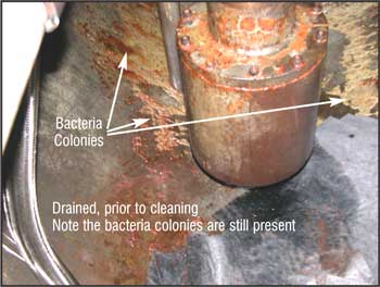
Why Temporary Filtration is Crucial for Process Equipment
Temporary filtration of hydraulic and lube oil systems is an efficient, cost-effective way to prevent problems before they happen. Often overlooked and underestimated, temporary filtration provides key benefits to the oil and gas industry. These include:
- Stopping materials from contaminating a system before they can cause damage, downtime, or failure
- Preventing premature equipment failure caused by plugged lines or damaged bearings
- Eliminating contaminants of all sizes, particularly on water and condensate systems — both before system startup and during active operations
- Removing particles and debris that a visual inspection and other methods miss
- Reducing or completely preventing operational problems caused by contamination
In addition, temporary filtration is a highly cost-effective method that saves money in the long-term.
The Importance of Filter Selection and System Setup
 The key to a good temporary filtration system is selecting the right filters and setup. There are several key factors to consider to ensure you get effective filters that work with your system:
- Micron level rating — how fine a particle filters can catch
- ISO Standard 4406:1999, which covers hydraulic fluid contaminants, requires filtration of solid particles as small as four microns in the oil
- For context, a micron (μm) is one-thousandth of a millimeter — 0.00004. Traditional filtration can only remove particles to about 1 μm. And the smallest particle visible to the human eye is 25 μm; a human hair is about 100 μm wide.
- Rating: absolute vs. nominal
- Absolute — remove 98%+ of contaminants in one pass
- Nominal — remove 50% – 97% of contaminants in one pass (varies by manufacturer)
- Ability to withstand various process conditions — check manufacturer recommendations for the following to ensure proper filter operation:
- Temperature
- Pressure
- Flow rate
Selecting the right filter and doing a proper setup is a specialty area of RIG’s. We can walk you through the process and ensure both critical equipment safety and minimal downtime during setup and breakdown.
About Reliable Industrial Group
At RIG, we’re one of the most trusted oil diagnostic, flushing and cleaning service providers for plants worldwide. We’ve served the biggest names in the oil and gas, energy, petrochemical, and refinery industries. Our highly trained and certified professionals are experts in lube oil flushing and have deep experience delivering projects quickly and on budget.
Why and How to Test New Oil Deliveries
Have you ever gotten milk from the grocery and later opened it only to find it had already gone bad? Bought a carton of eggs and found a couple were cracked? These things happen. Even if 99.999 percent of the time everything is perfect, that .001 percent can pose a big risk to your health. Just like those eggs from the store, machine oil can be defective and pose risks to the health of your machinery.
The key is not to allow defective products into your machine systems—that’s where testing is mission-critical. In this article, we’ll walk you through the absolute must-checks before you put your new oil into service.
A Word on Filtration
While many facilities filter their oil, filtration only removes dirt and particles, not the dozens of other contaminants and potential issues that can lurk, hidden in your oils. As such, we highly recommend proper testing for your lubricants.
Test Your Oil for Yourself
Some lubricant suppliers offer oil analysis services, wherein you could send your supplier a sample of newly delivered oil and have them test it. But there’s an inherent conflict of interest involved. While most are honorable, and you can trust them, it’s best to test at least some of the oil with an independent, third-party lab to confirm the results from your supplier’s lab.
Define Your Acceptable Quality Limit (AQL)
The first step in testing is to know what level of quality and consistency you need from your supplier—bottom line, you will get some defective oil, sometime. We do this using the acceptable quality limit (AQL) measure.
An (AQL) is the worst process average (a percentage) you can accept, prescribing the range of the number of defective components considered acceptable when random sampling those components during inspections.
Component defects fall into three categories (specified by the manufacturer):
- Critical
- Major
- Minor
What are your product quality controls? Is your AQL 95, 97 or 99.99 percent? As you set this, keep in mind small percentages on a large scale can create massive waste.
For example, the world’s biggest oil producer refines 241 million gallons of oil each day. With an AQL of 99.9 percent, that’s 241,000 gallons of defective oil per day—88 million gallons per year.
Bottom line, you can’t know your oil is acceptable if you don’t sample and test it, and you’ll need a nice, high quality standard that your supplier can still meet.
Once you’ve defined your AQL, it’s time to start testing for a variety of potential issues.
Types of Testing
Several types of testing can quickly tell you whether or not the brand new oil delivered to you is, in fact, suitable for your system:
- Viscosity Testing—Test with viscometers to ensure you get the correct grade (if your oil is too low a grade, it can massively impact your system)
- Particle Counting—Will help you determine how much filtration is necessary; you can use many quick, simple particle counters
- Offsite Testing—After viscosity and particle tests are performed, it’s best to take your oil to a third-party lab offsite that can run a series of tests
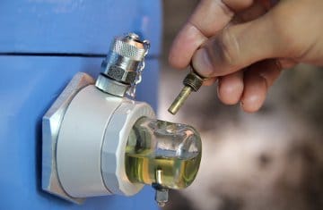
Drawing a Proper Oil Sample
The first key to proper testing is taking a proper oil sample. Here’s a step-by-step guide to help you through the process.
- Preparation
- Confirm the port ID plaque matches the work order
- Remove plug from tank opening
- Clean any exposed ports
- Hardware flushing
- Insert one end of your new nylon tubing into tank and the other end into vacuum pump; don’t tighten the knurled nut on the sampler to allow air to vent during sampling
- Loosely thread on the purge bottle
- Purge 10x estimated dead volume by pumping vacuum pump
- Loosen knurled nut to stop flow
- Remove flush bottle
- Sample bottle preparation
- Open sampling bottle
- Tightly thread sampling bottle onto sampling pump (nylon tubing end must puncture bag)
- Sampling
- Pull vacuum pump handle to extract oil sample
- Fill bottle no more than 75 percent full
- Stop oil flow by loosening knurled nut to break vacuum
- Extract tubing from tank
- Labeling
- Unthread sampling bottle from vacuum sampler
- Tightly secure cap without opening plastic bag
- Write required data on label
- Attach label to sampling bottle (if it’s not already attached)
- Cleaning
- Detach and discard tubing
- Clean sampling pump and place in a plastic bag
- Wipe clean and reinstall dust cap on sampling valve
- Wipe any fluid spilled on machine
- Dispose purged fluid, nylon tubing and any used, lint-free cloth (in accordance with your plant’s environmental policy)
Incoming Oil Tests
We recommend conducting the following tests for incoming oil:
- Viscosity at 40 degrees C (ASTM D445)
- Viscosity at 100 degrees C (ASTM D445)
- ISO particle count (ASTM D7647)
- Acid number (ASTM D664, D2896, D974, D3339)
- Karl Fischer moisture (ASTM D1744 or D6304)
- Elemental spectroscopy (ASTM D5185, D6595)
- Fourier transform infrared (FTIR) spectroscopy (ASTM E2412)
Tests by Fluid Type
Compressor, Gear, R&O and Turbine Oils:
- Color (ASTM D1500)
- Foam stability/tendency (ASTM D892)
- Demulsibility (ASTM D1401, D2711)
- Linear sweep voltammetry (ASTM D6810, D6971)
Hydraulic and Motor Oils:
- Varnish potential (ASTM D7843)
- RPVOT (ASTM D2272)
Maintain Top Cleanliness Standards
The health of your equipment and machine systems depends on the quality of your oil. Sub-par oil can cause component failures, equipment malfunctions and costly plant downtime. It’s crucial to your oil and your plant that your oil analysis program provides for proper oil sampling and testing of new oil deliveries.
At Reliable Industrial Group, we can help. We have more than 15 years of experience in oil sampling, analysis, testing, cleaning and flushing. We’ve helped major plants worldwide ensure total oil quality in their machine systems, extending the life of critical components, equipment and whole systems. Partnering with independent, third-party testing services, we ensure total peace of mind for your lubricants and your plant.
Challenges to Combined-Cycle Plant Steam Blowing Procedures
Combined cycle plants using gas and steam turbines in parallel present a special set of challenges during cleaning. Any missed debris can cause millions of dollars of damage to the steam turbine if the procedure is performed incorrectly, and variances in pressure tolerance between a steam and gas turbine often mean steam blowing must be done in sections.
Several specific design factors must be carefully planned for in a combined cycle steam blow operation. RIG’s technicians always perform a plant walk down prior to steam blow services, but combined-cycle plants require extra engineering and planning time to address the following:
- Stage Planning – Multiple blow stages are often required in combined cycle plants. When more than one Once Through Steam Generator (OTSG) or Heat Recovery Steam Generator (HRSG) is present, they will all need to be run and cleaned simultaneously due to internal temperature gradients but may require different steam pressures for effective cleaning. In addition, piping configurations may require several cleaning stages to ensure every section of pipe is addressed safely. Proper stage and section planning are the most critical part of a combined cycle plant steam blowing procedure.
- Minimizing Water Requirements – Steam blowing requires water and most combined cycle plants have minimal water reserves on-site. When required, a temporary water source with boiler feed quality water may be brought in. But this is expensive, so we make sure to design a steam blowing process that minimizes water requirements for feed water, attemperating water, and quenching water but still gets the job done with a CFR greater than one.
- Thermal Cycle Planning – Thermal cycling is a technique we use during combined-cycle blows to make the process more efficient. During thermal cycling we cool piping down periodically so that mill scale and particulates are dislodged during expansion and contractor and are carried away on the steam flow during cleaning. Pipe configurations and cooling techniques must be evaluated and planned for ahead of time.
- OTSG or HRSG Feed Rates – Water feed rates to the (OTSG) or (HRSG) will be used to control steam flow during blowing. This is different than in regular steam blowing procedures where throttling mechanisms are used. Steam rates must be calculated to ensure a cleaning force ratio greater than one is achieved, but also have to be coordinated with gas turbine load settings. If multiple steam pressures will be required, steam attemperating may be required to meet the blow conditions but stay within designated maximum expansion limits.
- Sound Control – This requirement is not unique to combined cycle plants, but may require more temporary piping than normal setups. To ensure worker safety, allow other operations to continue during steam blowing, and safely collect debris, temporary piping is run from blow points to silencers. Silencers absorb sound, collect debris and exhaust steam upwards. We also bring steam temperatures down to saturation just before entering the silencers to further quench noise levels. But, all the temporary piping we plan to use must be engineered to be ASME B31.1 compliant and able to handle maximum blow conditions.
We have successfully completed combined-cycle steam blows throughout the U.S. and around the world. An experienced steam blow procedure company can mean the difference between extending your plant equipment’s life and millions of dollars in re-work and repairs. If you have any questions about steam blowing, combined cycle pre-commissioning or preventive maintenance, please reach out to talk with one of our technicians: 800-770-4510.